Lisa ·
Replace Video Board and Hard Drive
Nothing escapes the cruel hands of time, and due its intricate
construction. the Lisa is a particularly slow runner. However, repairs can
help restore a beleaguered machine found in a dumpster to near factory
standards (if you're lucky). Here are accounts of my
travails in fixing my Lisa; perhaps they can help you.
1. Replacing a Lisa Video Board
![[caution image]](Lisa_service/alert_caution.gif) |
: The following
procedure is not to be taken lightly. It is fraught with high
voltage and possible implosions. Negligence on your part, or even
following these directions exactly as written could result in shards of
phosphor-covered glass embedding themselves into your flesh or
other unfortunate occurances. I, Tom Stepleton, assume no
responsibility for ANY result of following these instructions for
replacing the video board on any Apple Lisa or any other purpose.
DO NOT attempt this repair unless you are CERTAIN of what you are
doing. I accomplished it solely from EXTREME caution and that
foolish will a reckless teenager has. BE CAREFUL and do NOT perform
this repair if there is a professional who will do it for
you!
|
Still interested?
Tools and Parts: Safety goggles, medium-shafted Philips-head screwdriver,
medium-shafted flathead screwdriver, alligator-clip wire, Apple Lisa Video
Board, film canisters (optional).
Always wear safety goggles during this procedure!
Step 1: Unplug everything from the machine and wait at least one day after
powering down the Lisa before
repairing. The Lisa will not drain the anode or the high voltage capacitorhref="
on shutdown; a charge might be retained for extended periods of time! I
took no chances and waited a week... there is no rush.
Step 2: Ground yourself and the Lisa chassis adequately and remove the
rear panel of the Lisa by turning the two hand screws left and pulling.
Pull out the card cage and set both aside. Remove the front panel and set
it aside. Now, in the rear of the Lisa, locate the two screws in the air
vents inside the top of the card cage cavity. Unscrew them; they will
remain in the top of the cavity and will not fall. From the rear of
the machine, lift up the top cover of the Lisa about two inches and slide
it forward one inch. You may now lift off the top cover and set it
aside. DON'T TOUCH ANYTHING YET!
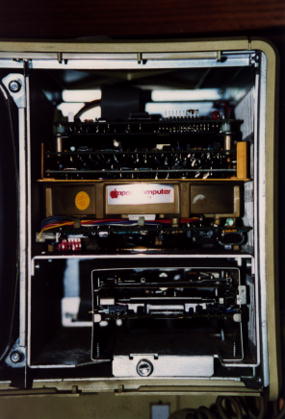
What you should see, looking from the rear of the Lisa: a metal sheet
covering the card cage cavity and power supply at the bottom, the top of
the Lisa Widget Controller to the far upper left (if you are using a
2/10), and the CRT cavity with
the Video Board at the lower left, flyback coil underneath the neck of the
CRT and to the right, and the speaker underneath the CRT at the upper
right. There should be a large red wire emerging from the top of the CRT
and going down into the flyback coil.
Step 3, Discharging the Anode: BEING ABSOLUTELY CERTAIN that the
Lisa is connected to some sort of ground and that you are at no risk
of shock, attach one end of the alligator-clip wire
to the shaft of the flathead screwdriver and the other end to the metal
frame of the Lisa. VERY CAREFULLY slide the screwdriver head underneath
the red rubber suction cup, not forcing anything. A little over a half
inch of my screwdriver went under when I did this. If there is any charge
left in the CRT or the high-voltage capacitor, it will dispel with a
small pop. It is a good idea to perform this operation even if you have
left the Lisa unplugged for an extended period of time. Take no
chances.
Step 5, Removing the CRT Neck Protector: In lieu of any technical term, I
decided to call the small metal box-like enclosure that protects the rear
end of the CRT the CRT neck protector. No matter what you call it, it
needs to be removed, and to do this you must remove the screws that hold
it. Before you do this, you must remove the main wires which go from the
white CRT cap to the video board from the white clips on the CRT neck
protector as well as the ground wire. Lift the main wires carefully from
the clips, being careful to not
twist the white CRT cap. After you have accomplished this, pull the
white ground wire from the CRT neck protector. Now you can
remove the screws. Some of these screws are accessed from the card cage
cavity and some from the CRT cavity. Use the medium-shafted Philips-head
screwdriver for this job.
![[note image]](Lisa_service/alert_note.gif) |
Handyman Tom's Helpful Hint: Are you a shutterbug?
If so, then you
undoubtedly have lots of film canisters lying around. Take as many film
canisters as there are screws in your project, arrange then in a pattern
similar to the places where the screws are located, then place each screw
in its respective canister. Not only will the screws stay put, you also
have a handy reference as to where to return the screws.
|
Step 6, Removing the Video Board Plugs: Locate the plugs going into the
video
board. There should be three of them: two smaller ones further up the
board and one large one lower on the board. These are seated quite firmly
and take some pulling to remove, and I had the blisters to prove it!
Exercise extreme care, however, as there is a vacuum inside thin glass
walls about three inches away! Also remember that printed-circuit board
bends; when you're pulling, hold the PCB in place to prevent it from
bending and subsequently cracking. After you have removed the first two
plugs and remembered which sockets they belong to, prepare yourself for
the monster eight-pin plug at the bottom. On the top and bottom there are
two clips you must push in before you can remove the plug. I spent hours
at this and suffered numerous blisters; for those of you wondering,
wrapping your fingers in duct tape does not work. I eventually broke off
one of the clips; all it took after that was some more pulling and the
plug was finally free.
Step 7, Removing the CRT Cap: Locate the round white plastic cap on the
tip of the CRT with the wires coming out of it. Ever so gently, being
careful not to push or twist the cap, pull it away from the end of the CRT
until the cap is completely off of the prongs. Set it aside. If the black
plastic cap from inside the white cap still remains over the very tip and
pins of
the tube,VERY CAREFULLY and with VERY LITTLE PRESSURE
use a knife to pry it away from the tip and pins, using a circular motion
to keep pressure even on all sides. Please remember that
there is a very thin wall of glass between the outside world and the
vacuum in the CRT. Treat it as if it were tissue paper. The black cap may
be brittle and it may fragment. If so, pry off the fragments with the
knife, letting them fall into a paper cup for disposal.
Step 8, Removing the Video Board: First, remove the two screws near
the top of the video board and keep them handy. Then, making sure that all
wires connected
to the Video Board are not obstructed and that all plugs are out, pull the
Video Board from the socket at the bottom of the CRT cavity. Discard.
Step 9, Inserting the new Video Board: Making sure that all the wires
connected to the new Video Board are not obstructed, lower the new Video
Board into the socket at the bottom of the CRT cavity. Press firmly.
Screw in the new Video Board with the same two screws you saved from
before.
Step 10, Inserting the Video Board Plugs: Remembering which plugs went
into which sockets, firmly insert the plugs into the video board, starting
with the lowest plug, the 8-pin, and working up. Make sure that you check
whether the plugs are going in right-side-up; although the plugs have
guides you may still be mistaken. Look for two notches on the plug; this
side is the top. The eight pin plug lacks these notches but rather has
a bar across the two four pin plugs. This bar must be facing upwards.
Step 11, Replacing the CRT Cap: Making sure there are no tangles, draw the
CRT cap back to the tip of the CRT, the wires forming a gentle curve,
ready to be inserted into the clips on the CRT neck protector. Slowly and
CAREFULLY slide the CRT cap onto the pins until they can no longer be
seen, making sure not to twist the cap. DO NOT FORCE!
Step 12, Attaching the CRT neck protector: Holding the CRT neck protector
in place, screw in the top screw first, then the two screws in the CRT
cavity adjacent to the CRT neck. Screw in the other screws. Gently, being
sure not to pull or twist the CRT cap, place the wires in their respective
clips.
Step 13, Closing the Lisa: Sitting behind the Lisa, draw the top cover
over the forward bar until the plastic prongs take hold. Replace the
screws inside the card cage cavity. Replace the front cover, the card
cage, and the rear cover.
Step 14, Testing: Turn it on. Stand back. If it works, you'll know.
Step 15, Bragging/Moaning: Although I hold no responsibility for what
happens when you use this procedure, no matter what the outcome, mail me
and let me know. The address is tom@tj.edu.inter.net.
Return to Contents
2. Replacing a Widget Internal Hard Drive
This is a much easier repair compared to the one above, and not nearly as
dangerous. In fact, the maintenance of the drives and the CPU, I/O, and
RAM boards is something that Apple probably intended any marginally handy
person to do -- what a difference from the early Macs! One of the things
that makes the Lisa such an interesting computer is that any area with
sufficiently low voltage is accessible for easy grokking. Anyway...
Tools and Parts: three hands, medium-shafted Philips-head screwdriver, film canisters
(optional).
![[stop image]](Lisa_service/alert_stop.gif) |
Before you proceed, make sure that the Lisa is plugged in and that (if the
Widget is functional enough) you have booted the Lisa from the hard disk
at least once after plugging it in last! The Lisa stores critical system
parameters (time/date, device info) in two places: the RAM and the boot
blocks of the boot disk. If the Lisa is unplugged, the parameters in the
RAM are lost and must be restored into RAM from the boot disk. Installing
a replacement Widget with no parameters in RAM may cause incorrect
information to be "restored" into parameter RAM. Incorrect parameter info
causes many system problems - be careful!
|
Step 1, Preparation: With the Lisa off, remove the front bezel by pushing
up on the two tabs underneath, then pulling out. Loosen the finger screw
beneath the floppy drive. Pull the entire drive assembly out of the cavity
and rest it upon a clean, anti-static surface. For reference, see
lisaguts.jpg.
Step 2, Disconnect: Looking down upon the assembly from the front, remove
carefully the three cables connecting the unit to the Lisa: the Widget
power cable, the Widget data cable, and the floppy cable. Next, disconnect
the two-lead fan cable attached to the top right of the uppermost board.
Memorize how the fan wire snakes up around the Widget--you will need to
know this later!
Step 3, Detach: Gently lay the assembly on one side. Remove the two screws
holding the Widget support plate in place in the stainless steel rack and
optionally place them in film canisters. Carefully
turn the assembly over, taking care that the Widget does not shift. Remove
the other two screws.
Step 4, Remove: Carefully set the assembly upright with a hand underneath
the Widget to prevent it from shifting. Gently spread the stainless steel
cage, pulling the fan wire away from the Widget in order to avoid a
tangle. Lift the Widget up and away from the cage and set it aside.
Step 5, Replace: Pull the fan wire taut and carefully spread the tainless
steel cage. Lower the new Widget into the proper position, while being
careful not to tug or scrape the fan wire. Try to keep the wire from geing
squashed--remember how it was before you removed the old Widget.
Step 6, Cleanup: Replace the holding screws to secure the Widget in the
cage. Reconnect the wires.
Step 7, End: Gently slide the cage back into the Lisa. Be very careful
that the cables do not get caught on screws inside the case. Apple mentions
this on the TIL, but I can't find it for the life of me! Replace the front
bezel and power up the Lisa. If the Widget hasn't been used for a while,
it may take a while before it actually starts to work! (or at least this
is my experience)
Return to Contents
Copyright ©1996 Tom
Stepleton. All rights reserved.
|

